

Optimize Signal Integrity in Flex Circuit PCBs
The natural flexibility of flex circuit PCBs can cause problems with signal integrity. This can lead to data corruption and reduced system performance. Optimizing signal integrity requires careful design considerations, simulation, and testing.
Optimal signal integrity is essential for high-speed circuits. This is because high-speed signals may need to travel long distances, which can increase signal delays and skew between traces. It is also important to ensure that the power distribution network is properly designed to provide consistent voltage to components and reduce electromagnetic interference (EMI). In addition, proper trace length matching, impedance control, and avoiding signal reflections are key factors in maintaining signal quality.
One of the most common ways that signal integrity is impacted is by copper work-hardening and fatigue during repeated flexing. The higher the number of layers in a flex section, the more likely it is to experience this problem. Therefore, it is important to decide up front how much flexing the section will be subjected to and use balanced construction techniques in order to minimize both of these issues. Using a higher-grade rolled annealed copper will also help, as it can be stretched longer before fatigue cracking and is springier in the Z deflection direction.
Another problem that can be caused by the flexing of a pcb is damage to copper traces from strain. This can be mitigated by using large bending angles with gradual curves to avoid excessive stress on the flex circuit’s copper layer. It is also important to choose a copper foil with a low work-hardening index that can be bent many times without fatigue. In addition, the flex circuit pcb should use solid ground planes instead of mesh ground planes, as a solid ground plane will allow any radiated EMI from the fiber weave cavities to be isolated and prevent it from radiating along the flex ribbon.
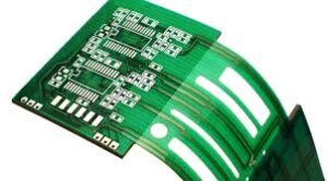
How to Optimize Signal Integrity in Flex Circuit PCBs
Finally, it is also important to limit the number of through-hole pads in a flex circuit and to use the smallest possible footprint for each component. This will help to reduce mechanical stress and improve signal integrity. In addition, using the coverlay “mask” openings to anchor each pad on both sides will help to prevent the pads from bending under the component pins during assembly.
These methods will require some additional effort in the design process and can slightly decrease the density of a flex circuit compared to a rigid board, but they are essential for the integrity of high-speed flex PCBs. This is especially true in high-frequency applications, where the higher frequencies can be more susceptible to interference and jitter. By using these techniques, it is possible to significantly increase the signal integrity of a flex circuit and get the most out of your CM’s manufacturing capabilities.
Flex circuits are also used in spacecraft and satellite sensors, where their flexibility and resistance to extreme conditions are crucial. They are integrated into the various sensor systems that monitor and control the spacecraft’s environment, ensuring accurate data collection and system functionality.