

functionality of a printed circuit prototype
A printed circuit prototype is a key step in PCB design and production, allowing designers to check the functionality of their work before mass-production. This guide walks through the steps of creating a high-quality PCB prototype and identifies common inspection and testing methods to help catch issues that could cause problems in manufacturing.
A PCB, or printed circuit board, is the vital connection between electronic components and the electrical signals that they route through them. These boards are found in many electronic devices, from computer monitors and laptops to flashlights and e-readers. PCBs are manufactured in several ways, but the process begins with a computer-aided design (CAD) program that allows designers to create schematics and lay out component locations and circuit traces on a physical board. Once the design is complete, it can be sent to a professional fabrication company for production.
Depending on the purpose of the printed circuit prototype, two different types of prototypes are created: a proof-of-concept and a working prototype. Proof-of-concept prototypes are simple and focused on replicating the primary function of a product without all of the bells and whistles that will be present in the final version of the device. Working prototypes, on the other hand, contain all of the planned features and capabilities of the device and are designed to be tested to identify any potential weaknesses or errors.
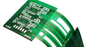
How do you test the functionality of a printed circuit prototype?
Once a working prototype has been completed, it must undergo both electrical and functional testing. The electrical test ensures that all of the components are connected properly, while the functional tests verify that the prototype performs all of the functions it was designed to do. This is the most important stage of PCB prototyping, as any flaws discovered during this phase will be much easier to fix than after a product is mass-produced.
Aside from testing for the correct connections, it’s also crucial to evaluate how well a working prototype holds up to mechanical and environmental stresses. A prototype can be subjected to a number of different tests, including vibration testing and thermal stress testing. This type of testing can be performed by a professional lab or by using a specialized software tool that can simulate how a device might perform in a real-world environment.
It’s also a good idea to have a graphical model made of the final product. This can be a 3D model made out of paper, clay or foam, or it can be an intangible mockup made with a variety of tools. A visual model is a great way to bring an intangible concept to life and can encourage discussions on the form factor of the finished product.
The most important thing to remember when it comes to testing a PCB prototype is that while what works in theory may work, it doesn’t always translate into reality. Taking the time to thoroughly test and inspect your prototypes will make it easier to catch errors and catch them before they lead to costly mistakes in production.